Sunday, November 24, 2013

Pennybot full pictures

I forgot to show off some full pictures of pennybot almost complete.  I still have the front and rear shields to make for the chassis.  Also I'm thinking of moving the single rear IR detector to be at the front centre.  After that it will be programming tuning.


Monday, October 7, 2013

IR top board


Top board

The IR board consisted of five IR detectors (and 0.1uF capacitors) and five accompanying IR leds.  There was also the PWM booster transistors and variable resistors to control the range of the IR leds.  I needed to be careful to try and avoid the PWM lines and the IR detector cabling from interfering with each other.  Otherwise the 38khz on the PWM wires could cause the IR detectors to falsely trigger.  So all the cabling was kept apart or if the wires had to cross then I tried to do so at right angles to reduce EMF.

Once all the parts were soldered up I did detection tests by measuring the voltage on the signal pin of the IR detector.  I found that to get the range I wanted I was almost at minimum resistor value of the IR led variable resistor circuit.  Instead of 100 ohms and a 1K variable resistor I probably should have gone of the absolute safe minimum of 50 ohms and a 500 ohm variable resistor.  However what I have worked ok.

Initially I was driving 3 IR leds off one transistor for the right side/left side / rear leds.  However I wasn't getting any signal from two of the IR leds.  It seems with the resistor value so low the voltage drop across the 3 leds was more than 5V.  The first led in series worked, but the second and third leds didn't.  I worked this out by measuring the frequency on the led pins and finding only the first led was at 38khz.  The others were zero.  However there was still voltage on each pin.  Odd.  So I added a third transistor of the rear IR led.  This means I have three transistor / resistor circuits for the leds.  One for the front two leds, one of the two side leds, one for the single rear led.  Perhaps I might add a second rear led, but space is very tight on the rear of the board.

With the IR detectors the two side detectors were up high and peering over the wheels.  Originally the front IR detectors were on top of the board looking down.  However due to the height of the front board this left a blind spot right at the front of pennybot.  Not the place you want a blind spot.  So I desoldered the front IR leds and detectors and put them under the board to get them lower.

Tuesday, September 3, 2013

Motor drive tests with SN754410


With the pic and SN 754410 ready to go it was time for a motor drive test.  But first the motors needed to be fixed up.  I did the standard practice of soldering 0.1uF capacitors from each motor terminal to the motor body and another capacitor across the motor terminals.  Then the wires from each terminal were twisted together and terminated in a 2 pin female header.

For the drive test I modified my full pennybot code and did a simple forward/back/left/right test.  Worked well but forward/back were backwards.  A quick modification in the code fixed that.  Also my dual colour leds were not symmetrical.  On forward one led was green, the other red.  So I flipped around one the leds and fixed that.  Probably could have worked that one out when initially soldering but I knew that I might get it wrong regardless so it was quicker to just do and fix if needed.

The drive test also showed one motor was slightly faster than the other.  Over a number of iterations pennybot was slowly turning around on it's starting position.  Nothing to fix there but it's good to be aware.

Now was time for the push test against Dumbbot, my first sumo bot which has only edge avoidance, no detection of opponents.  Both bots weighted in at 320gm.  Head to head pennybot couldn't move a stationary Dumbbot at all.  Those Tamiya rubber tyres Dumbbot hava obviously grip very well.  Dumbbot however with a much more geared down drive train and rubber tyres can push pennybot no worries at all.  Those skinny tyres Pennybot has just don't have the grip.  I can see why people buy the super sticky version of the tyres.  Hopefully at full 500gm weight things will be different.  As far as speed goes Pennybot approx. three times faster than Dumbbot.  So a design battle of strength vs speed will be had…once Pennybot has some eyes.

Finally since dumb is a rude word for 5 year olds Dumbbot is now know as Slowbot.  Soviet revisionism at it's best.

Sunday, August 25, 2013

Main board with PIC 16F628


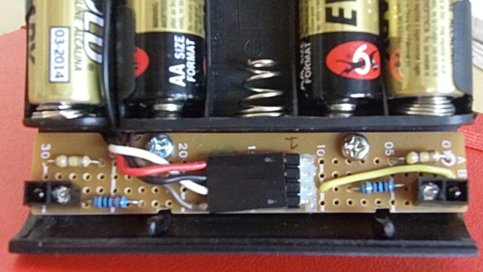
PIC 16F628 on the left, SN754410 on the right, LP2950 top right, ICSP top left, line sensor header bottom left, motor header bottom right

The main board of pennybot would consist of the following:

* PIC 16F628 microcontroller
* SN 754410 motor driver
* 5V power supply based around a LP2950
* connector pins for the motors, line sensor board, batteries, ICSP and IR sensor board

Lots to do and board space was limited so planning was needed.  A couple of hours shuffling components around and I had what I thought was a layout that would work.  Starting with the easy bits all the headers and IC chip sockets were soldered in first.  With that taking a couple of hours I started to remember how long it takes to put freeform circuit boards together from scratch.

The power supply was next.  This was also a major deviation from my original design.  Due to space and layout I moved the cutout switch in the circuit and deleted the filtering capacitor on the raw power line.  I also made some brain errors and kept making circuit hookups that meant the cutout switch didn't break the circuit.  Don't solder when tired!  I also had a false error in that when the cutoff switch was activated, I was still getting 5V.  However this was because at that stage I had lots of capacitors and no components to use up the stored charge.  The circuit was being cut but with nothing consuming power it takes awhile (minutes) for 5V to dissipate.  Always have at least a single led to drain out power.

Then it was a slow and steady task of connecting up everything else as per the schematic.  I did the Pic first so I could test the ICSP and make sure that was working before going further.  Whenever I'm wiring things up I like to do a small amount, test for short circuits, test functionality and then go onto the next item.  Trying to troubleshoot an entire board with everything soldered is just a recipe for tears.

For the connector to the IR board I used a 8 pin female header.  This header would double as the mounting socket too.  For the connection to power I decided to solder on the wires to the main board directly, rather than use a removable cable.  The connector would be on the chassis in the form of a female header recessed flush into the base plate.  To strengthen the connection I glued with two part epoxy the power wires on the main board.  I also epoxied the right angle header pins used for the motor and line sensor connections.  Anything that would be frequently connected and disconnected needed some extra support.  

For the most part things went well.  Another change that was made was the pull up resistor on pin RA4.  Originally this was 4.7K but that made the dual colour led very dim (with the red barely visible).  I dropped this to 1K.  I had never done this part of the design on the breadboard as I had used the dual colour leds as motor substitutes.  Always breadboard exactly what you are going to wire up.

Sunday, August 18, 2013

Line sensor board


Line sensor board

Now with a good and hopefully final chassis design it was time to pick up the soldering iron and start making things.  The first of the three boards to tackle was the line sensor board.  It would need to be very narrow to fit between the batteries and the front scoop.  The total parts list is small comprising of two leds, two IR phototransistors, 4 resistors and a 4 pin connector.  The four pin connector would be used for 5V power, ground and the two test point voltages from the sensors.  These voltages would be around 4V on the black surface and under 0.1V on the gloss white surface of the sumo ring edge.

For the four pin header instead of my usual molex connectors I used a standard right angle connector and the new headers I had recently purchased from Little Bird Electronics.  These headers are smaller than the molex ones but don't have a guide slot so can be inserted either way (and also the wrong way).

Once everything was soldered I drilled two holes mounting holes and tapped threads into the chassis.  All this drilling and tapping makes for a much better result but adds to the time.  Once a hole and drilled and tapped, then the bolt has to be cut to size as it can't come past the other side of the chassis base plate.  Much trial and error and test fits and cutting involved.  With the holes ready I used nylon spacers between the board and the chassis to get the position I wanted.

Lastly I made a 4 wire cable to connect to the main board.  Originally I started crimping a ribbon cable but then thought I was sure I already had a cable with a header on it in my salvage box.  Sure enough I did although the four header socket only had three wires.  Still saved some time and crimp pins.

After doing continuity test and shorts circuit tests I wired up the board to my bread board circuit and it worked fine.  Well it did until a further integration test showed the board and thus the sensors were too close to the ground.  The sensor voltages were only differing from 0.3V to 0.1v between the black surface and the white edge.  At the distance to the ground (under 3mm) even the flat black of the sumo ring was being detected.  This was solved by cutting the nylon spacers in half and reattaching the board.  With about 5mm distance between the board and the ring I was getting the behaviour and voltage differences  I wanted.  Next was onto the real work, the main board.

Wednesday, August 14, 2013

Pennybot chassis part 3


A chassis remade sans wheels

With the programming and breadboard design done, and the schematic finished it was time to start working on a board layout.  Not long into this process I worked out the chassis I had wasn't ideal.  It was only 8cm wide but 10cm long.  I didn't have room for a decent front scoop and the line sensors would be a very tight fit.  I was using a Tamiya base plate and I considered that I could simply rotate the board and easily make pennybot wider (out to 9.6cm) without having to change any of the holes I had drilled in the motor brackets which I really didn't want to have to make again.  Also the five AA batteries could now be mounted across the width of the chassis instead of along it so I would have more space at the front/rear and the centre of gravity would be all along the wheel axles.  I decided to cut down the motor brackets too so that they would only be the length of the motors themselves.  All this took a few hours on a Saturday.  The result was a wider pennybot with a better battery placement, but I had swapped one set of issues for another.  The Tamiya board is only 6cm wide, thus with the motors brackets and batteries there wasn't very much room (ie free 3mm holes in the board) on the front or rear to attach sensors, circuit boards, etc.  I could buy a bigger Tamiya board but had just done an order to Little Bird electronics and didn't want to pay postage again.  With a big sigh it was time to make a new chassis (number three) from scratch.

For my new chassis I wanted to make sure I remembered to do some key points.  I can get lost in problem fixing and forget the wider implications of design choices (and regret them later).  For all the mounting holes rather than drill straight through I would drill and tap 3mm threads.  This way I wouldn't need any bolts and wouldn't need space for the nuts.  That did mean I would have to cut down every bolt to size.  Bless the dremel.  I also wanted the base plate to be as big as I needed it.  Ie 10cm long and approx 8cm wide as the wheels and axles shafts would take the width to 10cm.  Looking through the scrap box I found an old plastic electronics project box which I never got round to using.  The box was curved on each side so cutting one half in the middle would give me a pre made scoop.  Also the dimensions fitted.  Some quick hacksaw and dremel work and I had a new base plate.  I put the axle shafts at the midway point and drilled and tapped the mounting holes.  I wasn't sure if the tapped screw holes into the plastic would be strong enough but they held.  Then the 5 AA batteries were placed underneath and things were looking good.


Batteries and sneak peak at the sensor board

Next up would be the front line sensor board.

Monday, August 5, 2013

Schematic and DesignSpark review


After getting the breadboard version of pennybot working it was time to draw up the schematic.  I first roughed it out on paper and then looked at what software to draw it up properly.  Normally I would use TinyCad as I had for my previous designs.  However I had in mind that I might want to have a professional pcb made up so I needed something with the functionality to generate the gerber files, drill plots, etc.

RS Components now have free schematic and pcb layout software package called DesignSpark.  Currently it runs only on Windows.  What is great about the software is the very extensive parts library and the option to link directly into RS Component's online store and search for parts, then download the schematic diagram and pcb layout information of that part.  Note that not all the components in RS components store are currently have this setup.  Free to use but you need to register to save your files.

Designspark comes with a nice tutorial which covers the process of schematic design, creating a pcb from that schematic and finally generating a BOM, gerber files, design reports, etc.  All in all very nice.  The best feature for me was the ease of generating a pcb and being able to generate a 3D view all in the one tool.

So final opinion?  I think I will keep trying out Designspark and use it for all my schematics going forward.  I'm sure the part library will only grow over time and the pcb layout functionality is very nice.

While originally keen to have a pcb made the cost has put me off.  The usual American offerings (expresspcb) are out due to postage costs.  There are local options (iTead for example) but for a one off board I'm still looking at the $80+ mark.  Point to point soldering here I come... once I work out the board layout.

Wednesday, July 31, 2013

Connecting the PNA4602 IR sensors to the PIC 16F628


As the PIC 16F628 has 5 interrupts (RB0/4-7) my design for the PNA4602 IR detectors is to have 5 detectors in total to detect the other sumo bot in the ring.  Two would be forward facing and one each for the left side/right side/rear.  The two forward detectors would operate in a crossed over (i.e. cross eyed) setup with the right detector looking left and the left detector looking right.  This would result in an overlap region at the front of pennybot.  Thus my detection regions are

forward left
directly forward (ie detected by both front sensors)
forward right
right side
rear
left side

I assigned the rear sensor to RB0 and the other four IR detectors to RB4-7.  I did this because I was toying with the idea of removing the rear IR sensor and instead using the RB0 interrupt pin for a front bump (ie micro switch) sensor.  It seemed a good way to separate between the two sets of interrupt pins.

To test each IR sensor the line was grounded as the PNA4602 goes low when a signal is detected.  This way the logic of what direction to turn depending on what sensor was activated could be easily tested.

On an aside two of the interrupt lines (RB6-7) are used for programming.  Since these two pins are normally at 5V (due to the PNA4602 output pin being high normally) this interfered with the in-circuit programming of the device.  After doing some web research the standard workaround for this was to put a resistor between the PicKit3 programmer and the rest of the circuit.   So going from the PNA4602 I have for both RB6 and RB7

PNA4602 -- 8.2K ohm resistor -- PIC16F628 RB6/7
    |
    -- PicKit3

Wednesday, February 27, 2013

PIC 16F628 and PNA4602 IR detectors

Each pin on the PIC 16F628 can only source 25mA.  To drive the IR leds I needed to use a transistor.  I selected a BC549 as it was listed as a signal transistor.  The voltage drop across each led was approx 1.2V so I should be able to drive 3 leds on a 5V line with a transistor.  Since I needed at least 5 IR leds (2 front, 1 left, 1 right, 1 back) I would need two transistors.  Next I had to calculate the minimum resistor value I could have that wouldn't result in more than 50mA being put through each led (the maximum an led could handle).  Initially I went with a very conservative resistor value of 1K. Doing number I found the minimum resistance as below:

2 IR leds

v/I = R
(5-(1.2*2)) / 50mA = R
52ohm = R


3 IR leds

v/I = R
(5-(1.2*3)) / 50mA = R
28ohm = R

For my initial tests I used just a single transistor with 3 IR leds connected.  Next was connecting up a single IR detector to the PIC.  I initially wanted to trial just one detector and a few IR leds in order to do range tests.  More on that later.

I used some PNA4602 detectors (the TSOP4038 seems more common now) which I had purchased from Solarbotics some time ago.  Yes, I was buying parts years before I got around to using them.  As widely recommended I put a 0.1uF capacitor across the power rail close to the detector.  The output of the detector went to pin RB4, one of the interrupt capable pins.  I setup in the ISR section that when the detector registered a hit, to turn left (thus changing one of the bicolor leds I've substituted for motors during testing).  Due to the blinking led loop I had in the main loop I could see when the detector (and thus ISR) was triggered.  Ie when I was in the ISR section the blinking led wouldn't be blinking.  Thus I had a double visual check that the detector was working as one of the dual colour leds I was using instead of motors would change color and in addition the blinking status led would stop blinking.  Now for range tests.

On my breadboard the IR leds and IR detector were approx a hand length apart and both pointing up at the ceiling.  Also I replaced the initial 1K resistor with my Variable resister box so I could adjust the power sent to the IR leds and thus the detector range.  So holding a ruler upright I slowly lowered my hand down the ruler.  I was looking for two things.  When the blinking led (from the main loop) stopped blinking, which would show the ISR had been entered.  The second was when the dual color led changed color from red to a solid green (not just a flickering green).  The results are below.

ResistanceDetectFull-Green
930ohm35cm18cm
530ohm43cm30cm
140ohm60cm+45cm

In the final circuit I plan to use a 1K variable resistor with the minimum safe resistor in series so I can tune on the fly.  The two front IR leds will be on one variable resistor, the left/right/rear IR leds will be on a second variable resistor.

Monday, January 21, 2013

SN754410 motor IC issues

By this stage I had a PWM signal and line detection working.  I decided it was time to integrate the two software components and the motor driver chip so I could observe the output of the logic decisions based on sensor inputs.  For the motor driver I used a SN754410 chip.  I had used this on a previous robot (squarebot) and I had a spare chip.  For testing instead of using motors I used dual colour leds to show the direction of the motors.  When the motor is going in one direction the led colour will be red, in the other direction the colour will be green.  I find the constant motor buzz gets distracting after awhile.  Also batteries die a lot faster.

I setup the logic so that when a line edge was detected the robot would turn away (ie right sensor detects a white line, turn left) or reverse if both line sensors were activated.  This wiring between the PIC and the SN754410 was quite simple with four outputs from the PIC going to the 4 H-bridge inputs on the SN754410.  The enable pins on the SN754410 I pulled high.  The motor power input came from the regulated 5V line.

In normal go forward mode this was fine.  However when the logic was to turn right all the leds went very dull.  Then I started seeing lock ups on the microcontroller.  Also the regulated 5V line would drop to under 3.5V when the motor chip was doing a "turn right".  I wasn't expecting the two motor leds to be drawing that much current so instead of the regulated 5V line I used an external battery pack for the SN754410 motor power input.  That stopped the led dimming.  However I knew that two leds with current limiting resistors shouldn't cause this.  

I then started to try and track down, was the issue related the the led/motor chip/microcontoller/something else.  Swapping parts showed that the leds were fine, thus it was when the PIC was saying turn right and the motor chip was doing so.  Swapping around the cabling from the PIC to the SN754410 show that the issue was with just one of the H-bridges on the SN754410.  So only when the H-bridge was having a certain output pin high did I see a high current draw.  The current draw went from 55mA up to 270mA when this was occurring.  Well past the limits of what a 9V battery can provide, hence the brownouts.  Taking the SN754410 from squarebot and swapping it in, no excessive current draw issue.  I had a dud SN754410 chip.  I binned that one and ordered 5 more from ebay that night.  Just love all these China/Hong Kong sellers with free shipping.

Now with my motor chip issues sorted it was time to move onto working with the IR part of the design.