Friday, July 3, 2009

TinyCad review

As my robots have progressed from being other people's designs to my own I decided it was time to start properly documenting the designs. While reverse engineering is always possible having a clear schematic makes referral much easier. Nudgebot was the first project where I considered it complex enough to invest the time in learning how to use a schematic/cad program.

Before I started the search I had a few requirements
  • free if possible. I'm just not doing this enough to justify the cost of software.
  • recent. No 15 year old dos programs running in a dos emulator.
  • ease of use over functionality. I have limited time to learn and use a software package. I don't see my designs ever being that esoteric so a simple program which is easy to use is better than the "greatest software package ever" (tm) which needs a full week course to learn.
  • a CAD program that feeds into a PCB generation program, and the PCB generation program produces industry standard layouts (ie layouts that I can send to a PCB manufacturer).
A quick canvas of the internet showed up plenty of likely candidates. Top of the list was the linux based gEDA package and the windows based TinyCad/Freepcb combo. Both were open source and free. TinyCad/Freepcb where GUI based, gEDA being a mix of CLI and GUI. Given the mixed OS environment I was running in and the fact both TinyCad and Freepcb ran fine under linux via wine I decided to give TinyCad/Freepcb a try.

As TinyCad is designed to a simple program there were no tutorials that I could find. However the in program help was a tutorial by proxy and covered enough to make getting started easy enough. The interface was extreme intuitive (always a mark of a successful interface design) and very clean. Simplicity of design with easy of use. A rare combination in freeware land. A quick summary...

The Pros
  • small install (5mb)
  • very intuitive and easy to use
  • good design checker (to pick up those human errors)
  • ability to generate netlists (in multiple formats include those used by Freepcb), parts lists and export designs as images.
  • very easy to create new components and add them to the component library
  • good support forum
  • runs on linux under wine

Now for the cons...

  • limited default library. A limited library of components (no 555 chip??). That is offset by the ease to make new components (which is going to be mandatory for most people).
  • default library could do with a clean up. Duplicates of some components in the different libraries.
  • resize of components all but broken. You can resize components quite easily. However once that is done they don't (unless you are very lucky) match up to the underlying component grid. This means you will connect components together, save a design, reload it and all those links will exist (ie lines joining components) but won't actually be connecting said components. The design checker will pick these up but the first time it happened it was a case of WTF. The moral here is never resize components. If you want one smaller/larger best to create anew component of the desired size. It's annoying the first time but after you are aware of the problem I don't see it as a major issue.
Summary

A good circuit schematic design tool which met and exceeded all my requirements. After taking half an hour to ready through the help I was making my first circuit without issue. Fell down the resize of components problem but a quick search on the forum resolved that issue. Within a few hours I had not only created a number of new components for the component library but had also completed the circuit design of Nudgebot. The end result was a semi professional looking schematic that I could put up on the web for others to enjoy.

Now to check out Freepcb...

Thursday, February 5, 2009

nudgebot part 5


Nudgebot front and rear

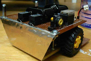
With the circuit complete the only item left to complete was the front shield/scoop. This would both protect the front circuits and sensors and be the scoop to push opponents. With the rest off the robot down I had under 1cm before I hit the 10cm length limit. This meant the scoop would be very steep. The angle end up being approx 80 degrees. So the scoop wouldn't be scooping under over robots but more of a battering shield.

Since I had weight to spare (nudgebot was under 300gm) I went for a heavier metal than what I used for the rear shield. I couldn't go to heavy otherwise I wouldn't be able to work it with the hand tools I have (no sheet metal bender I'm afraid). My standard way of bending sheet metal was to clamp it in a vice and using a small engineers hammer to work it over the bend.

My bottom attachment points were on the front sensor board. The top attachment points were one the front screw holes on the main board. I also wanted the shield to wrap around the front sides and curve over the top of the main board to protect the battery and sensor plugs.

This front sensor board was 7mm above the ground so I curved the bottom of the shield (rather than end in a straight edge) to reduce friction/potential for small bumps to be grabbed. While this seemed to work well I found I kept having scratch marks on the sumo ring. This was because a small part of the bottom of the shield was touching, not the entire bottom of the shield. This resulted in nudgebot bouncing as this one point would catch, scratch and then bounce up and repeat. Much bending and rebending of the bottom attachment points were attempted to fix this. In the end one of them broke off. Sheet metal can only be worked so much. So with only three attachment points the shield was still very rigid. I had learnt from the rear shield that having the metal under a slight amount of tension added a great deal of rigidity. Strangely enough after the bottom attachment point broke off the issue of the scratching from the bottom shield on the sumo ring went away and nudgebot was running with ease across the sumo ring. I cut my losses and stopped fiddling.

All that is left to do is maybe paint the front and rear shields black (to reduce IR detection) and add in some lead weights to get nudgebot up to the 500gm class weight limit.

nudgebot part 4


The brain board

The brain board was connected to the main board by a custom built six pin connector. On the main board I cut up a standard 8 pin DIL socket so I had two 3 pin connectors. These then went next to each other on the main board. The six connectors were power/ground/left sensor/right sensor/right motor/left motor. On the brain board I used an extended 6 pin connector (cut down from a 12 pin connector) that was approx 1.5cm long. This was then soldered into the main board.

Bottom of the brain board

However the first one I used turned out to be too short once the AA batteries were installed (always measure with everything in place!). This caused a problem as when I unsoldered it a number of the copper tracks came off too. Thus the second header was not as securely connected. Over time this weakened quite a bit and in the end I had to reinforce the entire lot with a big glob of epoxy glue to stop it from falling apart. Given the choice again I would just use a standard molex connector or like.

The brain board consisted of the 556 and 393 chips and associated variable resistors/resistors/etc. I used a small board (approx a third the size of the main board) and even that gave me plenty of room. I changed the circuit slightly from the original breadboard design by adding variable resistors to the time circuit in case it needed to make a few adjustments (in case my timings were off on the breadboard). After a few hours of careful soldering I was all done and ready for the first test.


Nudgebot read to go

Things started to look promising. Nudgebot drove well, detected the white line and turned, sometimes. Also there was a humming coming from the relays. Basically the relays were getting stuck (ie latching). The voltage would be at 3.5V approx and the relay wouldn't unlatch. This never happened on the breadboard design. After much trial and failure I did the obvious and used the 555 timer chip from the breadboard instead of the one I purchased for the brain board. Total success. Why were my two 556 timer chips so different? Well the issue was the design. When using a 555 to drive a relay you need a diode in series to prevent latch up. The book I had got the 555 design from specifically mentions it. I had just missed it and the breadboard 556 timer chip obviously handled this better than the other one. So I went with the breadboard 556 timer chip with a todo note for adding in the diodes in series when I get time.

With the bread board done the circuit was finished. Nudgebot worked great. It travelled well, detected the white line without issue, turned, etc. Only quibbles were the values I used for the variable resistors in the timing circuit were too high. At the lowest setting they triggered for approx 1 sec which with the motors resulted in a 100-160 degree turn. Fine but would be nice to have better control. Also as usual the motors performed differently with one motor slightly faster than the other and the turn being impacted by this. Again for a dumbbot this was fine. In fact the uneven turn meant that Nudgebot was unlikely to get stuck in a forward/reverse loop so it was kind of a blessing in disguise.

Sunday, January 11, 2009

nudgebot part 3


Nudgebot rear shield ready for abuse

Although sumobots aren't battlebots there is still going to be some wear and tear from bumps, falling off tables, etc. Looking at the rear section I thought there was a good chance that during bouts the motors cables might be damaged. So I decided to add a rear shield made out of light sheet metal to protect them.

The metal I used was from a Sun unipack disk enclosure. It originally was the shielding on the top of the disk enclosure. It is quite light but in the small size I was using and having it secured at four points it should be solid enough. I used some tin snips to cut out a rectangle of metal and then marked out the size of the bottom plate and cut at an angle to the top of the sheet. This was me trying to be fancy. I used a vice and small engineers hammer to work the metal into shape. Then I marked out and drilled the four attachment points (two top, two bottom). I had to be very careful with the drilling as even the 3mm drill would twist the sheet metal out of shape. Also on the top lip I had to cut out a recess around the components which I used tin snips to cut out. That was a bit rough so I should have used the cutting disk on my Dremel instead. A lesson learnt for when I get to making the front scoop and shield for the line sensors later on (and another reason I did the rear shield first - to work out all the things I shouldn't do).

Finally I will need to paint the rear shield (most likely black). Highly reflective sheet metal is light a flash light in the dark to infra-red detectors. Don't want nudgebot making things too easy for better sighted opponents.

Saturday, January 10, 2009

nudgebot part 2


Nudgebot engines and main board

Now with a reliable base it was time to start on the main base board. The first part to be done was mounting the 3V battery pack (2xAA batteries). This was mounted in the centre of the board. This was to keep the majority of the weight on the centre axis to imporve rotation of the bot. Once that was done I put in the two relays which will be used as the motor controllers. This was the same as trackbot. This setup has the advantage as it allows me to use 3 volt motors without needing to do dual power lines off one battery. Instead I have a regulated 5 volt line for all the circuit and plain "raw" 3 volts for the motors. This does mean I have two power supplies (9V and 3V). I used molex connectors for the engines as I knew I would be doing a lot of rework on the chassis so easy removal was a must.

Next was the 9V battery connector and the 5 volt power regulator. I used a 78L05 with various filtering capacitors. Rather than a power switch I used a two pin jumper as a switch. I also did the same for the 3V battery supply. This was to reduce not only space but also weight. Utility is much lower but I'm not seeing this bot being used every day.

With the 5V power supply available I setup the five second delay part of the circuit. This was formed from a resistor-capacitor circuit that was tuned to activate a relay and keep it powered for 5 seconds. This relay would be used to cut power to the rest of the circuit. Rather than have the circuit cut power to the logic chips (ie the 555 timer and sensor ciruits) instead I used the relay to cut power to the 3V power line. This was because the motor setup the motors are always on, either running in forward or reverse. These is no idle. So I needed to kill the motor power obviously. Also I setup the relay so that the NC would result in the circuit being connected. This way power drain is minimised. Some setups I have seen have the relay needing to be active (ie the NO pin completes the circuit) to complete the rest of the circuit. This always struck me as odd as it just drains the battery. Finally a small push button switch was added at the back of nudbebot to activate the time delay circuit. A quick test and everything worked fine. Hit the button and the motors cut out for approx 5.5 seconds.


Main board with the 5 second delay circuit on the right and the 5V power supply next to the 3v battery pack

I also did some push tests. The high torque gearing worked well with nudgebot being able to push 500gm without any issue. The only problem I can see is the wheels. They have a tread on them. Normally this is fine but in a pushing setup tread just means you don't have the maximum amount of wheel on the ground. Perhaps some sticky rubber bands will be added later.

Friday, January 9, 2009

was dumbbot, now nudgebot


Nudgebot engine base

After some push test with dumbbot I found a few issues. First was some 'crabbing' by dumbbot. This was where the chassis would go sideways rather than straight ahead. This was due to the pulleys being pulled back at different angles. That was countered slightly but it was always going to be an issue as the axle mounts are quite loose.

I also found the power transfer from the motors wasn't great. There was a degree of belt slippage, but that was expected. However on the higher end of the push tests (ie .5kg dumbbot pushing .5kg opponent) there was very little pushing going on and a lot of belt slipping. I added some heat shink wrap on the engine shafts to try and reduce this but it was still an issue.

All these things together made me think that although the pulley drive system was cool it wasn't the best design. A sumobot that went sideways instead of straight that could barely push the 500gm weight wasn't good enough. Even those dumbbot was going to be an opponent I still wanted it to be up to standard. Thus a redesign was considered.

I needed a drive system that was solid and had the torque needed. The gearhead motors available to me were too long to sit side by side so I would have to have the axles at a 90 degree angle to the engine shafts. Annoying and hard to engineer properly. So I went back to my good friends at Tamiya and decided to use the dual gear motor set that I used for Trackbot. It fits well on the base plate obviously and was under 10cm wide. I used the lowest gearing ratio that gave 2276gf/cm and only did 38rpm. With two motors I should be able to push anything.

I used the same wheels but I sanded down the wheel hubs to reduce their width. I also cut the axles from approx 5cm to 4.7cm. Again this was to reduce the width so the engines plus wheels were under 10cm. With this extra work they were. A lot of grinding, cutting and fiddling around but the end result was a much better engine base. No point having a working circuit which is going to be let down in the pushing department.