Sunday, January 11, 2009

nudgebot part 3


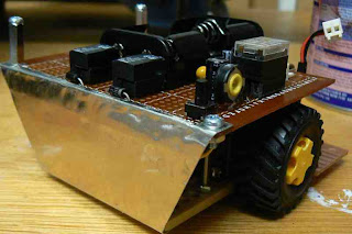
Nudgebot rear shield ready for abuse

Although sumobots aren't battlebots there is still going to be some wear and tear from bumps, falling off tables, etc. Looking at the rear section I thought there was a good chance that during bouts the motors cables might be damaged. So I decided to add a rear shield made out of light sheet metal to protect them.

The metal I used was from a Sun unipack disk enclosure. It originally was the shielding on the top of the disk enclosure. It is quite light but in the small size I was using and having it secured at four points it should be solid enough. I used some tin snips to cut out a rectangle of metal and then marked out the size of the bottom plate and cut at an angle to the top of the sheet. This was me trying to be fancy. I used a vice and small engineers hammer to work the metal into shape. Then I marked out and drilled the four attachment points (two top, two bottom). I had to be very careful with the drilling as even the 3mm drill would twist the sheet metal out of shape. Also on the top lip I had to cut out a recess around the components which I used tin snips to cut out. That was a bit rough so I should have used the cutting disk on my Dremel instead. A lesson learnt for when I get to making the front scoop and shield for the line sensors later on (and another reason I did the rear shield first - to work out all the things I shouldn't do).

Finally I will need to paint the rear shield (most likely black). Highly reflective sheet metal is light a flash light in the dark to infra-red detectors. Don't want nudgebot making things too easy for better sighted opponents.

Saturday, January 10, 2009

nudgebot part 2


Nudgebot engines and main board

Now with a reliable base it was time to start on the main base board. The first part to be done was mounting the 3V battery pack (2xAA batteries). This was mounted in the centre of the board. This was to keep the majority of the weight on the centre axis to imporve rotation of the bot. Once that was done I put in the two relays which will be used as the motor controllers. This was the same as trackbot. This setup has the advantage as it allows me to use 3 volt motors without needing to do dual power lines off one battery. Instead I have a regulated 5 volt line for all the circuit and plain "raw" 3 volts for the motors. This does mean I have two power supplies (9V and 3V). I used molex connectors for the engines as I knew I would be doing a lot of rework on the chassis so easy removal was a must.

Next was the 9V battery connector and the 5 volt power regulator. I used a 78L05 with various filtering capacitors. Rather than a power switch I used a two pin jumper as a switch. I also did the same for the 3V battery supply. This was to reduce not only space but also weight. Utility is much lower but I'm not seeing this bot being used every day.

With the 5V power supply available I setup the five second delay part of the circuit. This was formed from a resistor-capacitor circuit that was tuned to activate a relay and keep it powered for 5 seconds. This relay would be used to cut power to the rest of the circuit. Rather than have the circuit cut power to the logic chips (ie the 555 timer and sensor ciruits) instead I used the relay to cut power to the 3V power line. This was because the motor setup the motors are always on, either running in forward or reverse. These is no idle. So I needed to kill the motor power obviously. Also I setup the relay so that the NC would result in the circuit being connected. This way power drain is minimised. Some setups I have seen have the relay needing to be active (ie the NO pin completes the circuit) to complete the rest of the circuit. This always struck me as odd as it just drains the battery. Finally a small push button switch was added at the back of nudbebot to activate the time delay circuit. A quick test and everything worked fine. Hit the button and the motors cut out for approx 5.5 seconds.


Main board with the 5 second delay circuit on the right and the 5V power supply next to the 3v battery pack

I also did some push tests. The high torque gearing worked well with nudgebot being able to push 500gm without any issue. The only problem I can see is the wheels. They have a tread on them. Normally this is fine but in a pushing setup tread just means you don't have the maximum amount of wheel on the ground. Perhaps some sticky rubber bands will be added later.

Friday, January 9, 2009

was dumbbot, now nudgebot


Nudgebot engine base

After some push test with dumbbot I found a few issues. First was some 'crabbing' by dumbbot. This was where the chassis would go sideways rather than straight ahead. This was due to the pulleys being pulled back at different angles. That was countered slightly but it was always going to be an issue as the axle mounts are quite loose.

I also found the power transfer from the motors wasn't great. There was a degree of belt slippage, but that was expected. However on the higher end of the push tests (ie .5kg dumbbot pushing .5kg opponent) there was very little pushing going on and a lot of belt slipping. I added some heat shink wrap on the engine shafts to try and reduce this but it was still an issue.

All these things together made me think that although the pulley drive system was cool it wasn't the best design. A sumobot that went sideways instead of straight that could barely push the 500gm weight wasn't good enough. Even those dumbbot was going to be an opponent I still wanted it to be up to standard. Thus a redesign was considered.

I needed a drive system that was solid and had the torque needed. The gearhead motors available to me were too long to sit side by side so I would have to have the axles at a 90 degree angle to the engine shafts. Annoying and hard to engineer properly. So I went back to my good friends at Tamiya and decided to use the dual gear motor set that I used for Trackbot. It fits well on the base plate obviously and was under 10cm wide. I used the lowest gearing ratio that gave 2276gf/cm and only did 38rpm. With two motors I should be able to push anything.

I used the same wheels but I sanded down the wheel hubs to reduce their width. I also cut the axles from approx 5cm to 4.7cm. Again this was to reduce the width so the engines plus wheels were under 10cm. With this extra work they were. A lot of grinding, cutting and fiddling around but the end result was a much better engine base. No point having a working circuit which is going to be let down in the pushing department.