Sunday, July 13, 2014

Final build photos of pennybot

I realised that I didn't have any full build pictures of pennybot here.  Now I do.

Ready to scoop

All three front facing IR detectors
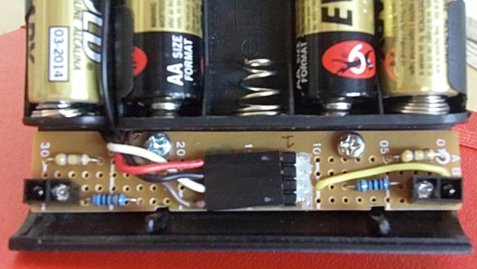

Wednesday, June 25, 2014

Pennybot pic16f628 asm code

The full pennybot asm code..

include "P16F628A.INC" ;include the defaults for the chip
list p=16f628a
__config (_CP_OFF & _CPD_OFF & _PWRTE_OFF & _WDT_OFF & _INTRC_OSC_NOCLKOUT & _LVP_OFF & _BOREN_OFF & _MCLRE_OFF)

; pin out list
; PORTA RA
; 0 comparator input - right line sensor
; 1 comparator input - left line sensor
; 2 comparator input  - reference voltage
; 3 motor driver output A - right motor
; 4 motor driver output A - right motor
;                       - open collector - needs pull up resistor to 5V to go high
; 5 unused - input only
; 6 motor driver output B - left motor
; 7 motor driver output B - left motor

; PORTB RB
; 0 IR detector input - front - IR detectors go low on signal, normally 5V
; 1 unused
; 2 status led - blinks while code in main loop
; 3 digital output, PWM
; 4 IR detector input - left  front  - IR detectors go low on signal, normally 5V
; 5 IR detector input - right front
; 6 IR detector input - left side
; 7 IR detector input - right side

; general variables
cblock 0x20
count ; used in delay routine
count1 ; used in delay routine
counta ; used in delay routine
countb ; used in delay routine
        compcount   ; used in comparator compare
endc

#define W_TEMP  0x70 ; common memory area across all banks
#define STATUS_TEMP 0x71 ; temp vars for ISR

org 0x00
goto init

;
; ISR code
;
org 0x04
movwf   W_TEMP ; Save W & STATUS, etc
swapf   STATUS, W
bcf     STATUS, RP0
movwf   STATUS_TEMP ; end ISR save bits

btfsc PIR1, CMIF
call check_comp     ;check comparators - line detection
btfsc INTCON,INTF
    goto check_front_IR    ;check single front IR detector, skip other IR decectors
btfsc INTCON,RBIF
call check_IR       ;check other IR detectors
isr_exit
swapf   STATUS_TEMP, W   ; restore W & STATUS
movwf   STATUS
swapf   W_TEMP,F
swapf   W_TEMP,W
retfie                  ; end ISR restore bits

; end ISR code

init
; init steps are
                ; setup PORTA and PORTB pins as input/output
; halt motors
; delay 5 seconds
; setup comparator mode
; setup ir detectors - done as enable interrupt
; setup rear ir sensor
; setup 38khz, 50% duty cycle PWM
; enable interrupts


banksel TRISA ; set all pins in appropriate input/output
movlw b'00100111' ; RA5 always input
movwf TRISA ; set PORTA pins
movlw b'11110001'
movwf TRISB ; set PORTB pins

    call stop           ; motors halt

    banksel PORTB
    bsf PORTB,2         ; turn on test led

call Long_Delay ; delay 5-6 secs

banksel CMCON ; init comparator mode
movlw 0x03
    movwf CMCON ; CM<2:0> = 011
    call Delay10        ; delay 10 microseconds
    movf CMCON,F ; read cmcon to end change condition wrt interrupt setup
    bcf PIR1, CMIF ; clear pending interrupts
    banksel PIE1 ; select bank 1
    bsf PIE1, CMIE ; enable comparator interrupts

            ; setup and run 38khz pwm
banksel PR2         ; set pwm period
movlw   0x19 ; 0x19 == 25 decimal.  So via equation
movwf   PR2         ; 25+1 * 4 * 0.25 * 1 = 26 and 1/26 == 38khz ish
                        ; set pwm duty cycle to 50%
    banksel CCP1CON ; so need duty cycle to be half pwm period
            ; ie half (25+1)*4 -> 52 = 0x34
    movlw   0x0c ; since Tosc is in both pwm and duty cycle equation they cancel out
    movwf   CCP1CON ; remember split across bits 5/4 of ccp1con and ccpr1l
    movlw   0x0d ;  0x   0    d  0
    movwf   CCPR1L   ; duty cycle 0x34 - ie 52 decimal
    banksel T2CON ; set tmr2 prescaler
    movlw   0x00
    movwf   T2CON
    bsf T2CON, TMR2ON ; turn on timer 2


banksel INTCON ; enable interrupts
    bsf INTCON, RBIE    ; enable RB port interrupts (RB4-7)
    bsf INTCON, INTE    ; enable RB0 port interrupt
    bsf INTCON, PEIE ; enable peripheral interrupts
    bsf INTCON, GIE ; enable global interrupts

main
nop
    banksel PORTB
    bcf PORTB,2         ; turn off status led
call forward
goto main

;
; check front IR detector, go forward if something there
;
check_front_IR
    call Delay20        ; wait for signal to settle
    banksel PORTB
    btfss   PORTB,0     ; check RB0, low means we detected something
    call    forward   ; move ahead
    banksel INTCON
    bcf     INTCON,INTF    ; clear RB0 interrupt flag (maybe clear other IR interrupt flag?)
    goto isr_exit

; end check_front_IR

;
; check what IR detetor went off and change motors as needed
; low means we detected something
;

check_IR
    call Delay20        ; wait for signals to steady
    banksel PORTB
    btfss PORTB,6       ; check right side
    goto turnright_IR   ; turn right as something was there
    btfss PORTB,7       ; check left side
    goto turnleft_IR    ; turn left as something was there
    btfss PORTB,5       ; check left front
    call frontleft_IR
    btfss PORTB,4       ; check right front
    call frontright_IR
checkirexit
    banksel INTCON
    bcf INTCON,RBIF     ; clear interrupt flag
    return
turnright_IR
call fastright
goto checkirexit
turnleft_IR
call fastleft
goto checkirexit
frontright_IR
call slowright
goto checkirexit
frontleft_IR
call slowleft
goto checkirexit

; end check_IR


;
; check comparators function (line sensors)
; reverse if both sensors are active
check_comp
call Delay20        ; wait 20ms for input to get stable
banksel CMCON
btfsc CMCON,C1OUT   ; if c1out is 1
    bsf compcount,0     ; got a right sensor reading
    btfsc CMCON,C2OUT   ; if c2out is 1
    bsf compcount,1     ; got a left sensor
    movlw   d'3'        ; compcount is 0000 0011 if both sensors active ie 3
    subwf   compcount,0
    btfsc   STATUS,Z    ; was the result 0?
    goto comp_reverse   ; both sensors active, reverse, otherwise check again
btfsc CMCON,C1OUT   ; right sensor active
    goto comp_turnleft      ; turn right
    btfsc CMCON,C2OUT   ; left sensor active
    goto comp_turnright      ; turn left
compexit
bcf PIR1, CMIF      ; clear pending interrupts
return
comp_reverse
    call reverse        ; both sensors active, reverse
    call fastleft
goto compexit
comp_turnleft
call fastleft
goto compexit
comp_turnright
call fastright
goto compexit

; end check_comp

; motor drive functions

;
; halt both motors by setting both outputs high
;
stop
banksel PORTA
movlw b'11011000'
movwf PORTA
return

;
; forward on both motors
;
forward
banksel PORTA
movlw b'01001000'
movwf PORTA
    ;call    Delay255
    call    Delay50
return

;
; reverse on both motors
;
reverse
banksel PORTA
movlw b'10010000'
movwf PORTA
    call    Delay255
return

;
; turn right on spot
;
fastright
banksel PORTA
movlw b'10001000'
movwf PORTA
    call    Delay255
return

;
; turn right by stopping left motor
;
slowright
banksel PORTA
movlw b'11001000'
movwf PORTA
    call    Delay255
return

;
; turn left on the spot
;
fastleft
banksel PORTA
movlw b'01010000'
movwf PORTA
    call    Delay255
return

;
; turn left by stopping right motor
;
slowleft
banksel PORTA
movlw b'01011000'
movwf PORTA
    call    Delay255
return

; end motor functions

;
; Delay routines (based on 4MHz clock)
; http://www.piclist.com/techref/piclist/codegen/delay.htm

Long_Delay
        movlw  d'60'       ;delay 6 seconds
call Delay100W
return

Delay100W movwf count ;delay W x 100mS
d2 call Delay100 ;maximum delay 25.5 seconds
decfsz count ,f
goto d2
return

Delay255 movlw 0xff ;delay 255 mS
goto d0
Delay100 movlw d'100' ;delay 100mS
goto d0
Delay50 movlw d'50' ;delay 50mS
goto d0
Delay20 movlw d'20' ;delay 20mS
goto d0
Delay10 movlw d'10' ;delay 10mS
goto d0
Delay1 movlw d'1' ;delay 1mS
goto d0
Delay5 movlw 0x05 ;delay 5.000 ms (4 MHz clock)
d0 movwf count1
d1 movlw 0xC7      
movwf counta
movlw 0x01      
movwf countb
Delay_0 decfsz counta, f
goto $+2
decfsz countb, f
goto Delay_0

decfsz count1 ,f
goto d1
return

;end of Delay routines

end

Saturday, June 21, 2014

Pennybot finally makes it to the big time - sumobot finals


In order to get pennybot into the winner’s circle I needed to make a number of changes…

Realising that the rear IR sensor wasn’t really useful I unsoldered it and added it to the front of pennybot as a front sensor between the current left/right sensors.  This sensor was connected to the interrupt pin RB0.

I made a new metal scoop for the front with the bottom edge formed around a piece of wire for extra strength.  This scoop just scrapes the floor.  Great for lifting up opponents but terrible on the sumo ring paint job.

I went back to a much simpler code base for the IR detection function.  Firstly in the ISR section I check each interrupt flag to see what interrupt was triggered before calling that function.  Before I was running through all the sensor functions (line sensor/IR detectors) regardless.  Now with the direct front IR sensor being to RB0 I had three functions.  Firstly check the line sensors as staying within the ring is the most important behaviour.  Second check the direct front IR sensor (RB0) and go forward if that detects.  Once in this function skip the rest of the IR sensor checks before exiting the ISR code section.  This is to stop a false hit from making pennybot go left/right after a forward move.  Finally check the other IR sensors on RB4-7.

Also I removed all the loop and repeat checks.  Rather we go through the ISR code once and then out.  Previously I was getting stuck in function call loops that were going more than 8 deep and thus breaking as the stack would loop over itself.

Finally I changed the motor driving code for when there was a left front or right front detection.  Rather than turn on the spot we now do a slow right or left turn by braking one wheel (by making both motor inputs high) and only powering the other.  This results in a turn with the pivot point being the braked wheel rather than the centre of pennybot.

In previous bouts dumbbot was the winner 4 out of 5 matches.  The push strength dumbbot has was too much and it’s wheels too grippy for pennybot to push.  Now it was a different story.  Pennybot won every single match.  The new IR detection code worked great, the slow turns allow pennybot to track much better and the new scoop lifts up dumbbot slightly so it loses traction and can be pushed back.  Finally success.

The only minor points I’m considering to fix is the turn time on the line sensors.  Sometimes when there is line detection pennybot turns so far on the spot the other line sensor detects and we end up spinning on the spot.  The third IR emitter circuit (previously used for the rear IR emitter) is still on the board but unused.  Perhaps I will unsolder it but it seems more effort than it is worth.  Also I should add in a watchdog timer to get me out of unknown code failures.  The watchdog timer is one part of the pic programming I haven’t played with yet.

It’s been a long time but finally I can have a sumo battle.

pic16f628 and USART via a max232 chip

Max232 chip and associated capacitors.  3.5mm jack on the right.

While I was thinking out pennybot I was wondering how I could get more debug information out as the single blinking led I have currently isn’t much.  I remembered that the pic16f628 had usart onboard so a read up on it.  Only two pins were needed with a max232 chip to handle the voltage pumping to a RS232 connection. Sounded pretty easy.

However before this point I needed a usb to serial dongle and a serial terminal program for my Mac.  I already had a usb/serial adapter based on the pl2302 chip, a cheap ebay purchase.  I searched around and found the necessary drivers for Mac so the pl2302 would be detected.  Google is your friend for that.  For a terminal program some people suggested using the ‘script’ command but that didn’t work very well.  I then tried CoolTerm which was great and I fully recommend it.

For the max232 chip (and associated capacitors) I knew that I would want to use it both on my breadboard and possibly on future pic projects.  A standalone board was the best option.  I had a 4 pin (5v, GND, RX, TX) male header to connect the board to a breadboard or circuit and a stereo 3.5mm socket to connect the serial cable to.  The serial cable was a recycle job were I got an existing 9 pin cable, cut off one end and wired up RX, TX and GND to a 3.5mm male stereo plug.  It’s smaller than a full 9pin shell and is quite robust.  Now I will be reserving the USART pins on pic projects in future and having a 4 pin female header so I plug in my max232 board when needed.

Sunday, November 24, 2013

Pennybot full pictures

I forgot to show off some full pictures of pennybot almost complete.  I still have the front and rear shields to make for the chassis.  Also I'm thinking of moving the single rear IR detector to be at the front centre.  After that it will be programming tuning.


Monday, October 7, 2013

IR top board


Top board

The IR board consisted of five IR detectors (and 0.1uF capacitors) and five accompanying IR leds.  There was also the PWM booster transistors and variable resistors to control the range of the IR leds.  I needed to be careful to try and avoid the PWM lines and the IR detector cabling from interfering with each other.  Otherwise the 38khz on the PWM wires could cause the IR detectors to falsely trigger.  So all the cabling was kept apart or if the wires had to cross then I tried to do so at right angles to reduce EMF.

Once all the parts were soldered up I did detection tests by measuring the voltage on the signal pin of the IR detector.  I found that to get the range I wanted I was almost at minimum resistor value of the IR led variable resistor circuit.  Instead of 100 ohms and a 1K variable resistor I probably should have gone of the absolute safe minimum of 50 ohms and a 500 ohm variable resistor.  However what I have worked ok.

Initially I was driving 3 IR leds off one transistor for the right side/left side / rear leds.  However I wasn't getting any signal from two of the IR leds.  It seems with the resistor value so low the voltage drop across the 3 leds was more than 5V.  The first led in series worked, but the second and third leds didn't.  I worked this out by measuring the frequency on the led pins and finding only the first led was at 38khz.  The others were zero.  However there was still voltage on each pin.  Odd.  So I added a third transistor of the rear IR led.  This means I have three transistor / resistor circuits for the leds.  One for the front two leds, one of the two side leds, one for the single rear led.  Perhaps I might add a second rear led, but space is very tight on the rear of the board.

With the IR detectors the two side detectors were up high and peering over the wheels.  Originally the front IR detectors were on top of the board looking down.  However due to the height of the front board this left a blind spot right at the front of pennybot.  Not the place you want a blind spot.  So I desoldered the front IR leds and detectors and put them under the board to get them lower.

Tuesday, September 3, 2013

Motor drive tests with SN754410


With the pic and SN 754410 ready to go it was time for a motor drive test.  But first the motors needed to be fixed up.  I did the standard practice of soldering 0.1uF capacitors from each motor terminal to the motor body and another capacitor across the motor terminals.  Then the wires from each terminal were twisted together and terminated in a 2 pin female header.

For the drive test I modified my full pennybot code and did a simple forward/back/left/right test.  Worked well but forward/back were backwards.  A quick modification in the code fixed that.  Also my dual colour leds were not symmetrical.  On forward one led was green, the other red.  So I flipped around one the leds and fixed that.  Probably could have worked that one out when initially soldering but I knew that I might get it wrong regardless so it was quicker to just do and fix if needed.

The drive test also showed one motor was slightly faster than the other.  Over a number of iterations pennybot was slowly turning around on it's starting position.  Nothing to fix there but it's good to be aware.

Now was time for the push test against Dumbbot, my first sumo bot which has only edge avoidance, no detection of opponents.  Both bots weighted in at 320gm.  Head to head pennybot couldn't move a stationary Dumbbot at all.  Those Tamiya rubber tyres Dumbbot hava obviously grip very well.  Dumbbot however with a much more geared down drive train and rubber tyres can push pennybot no worries at all.  Those skinny tyres Pennybot has just don't have the grip.  I can see why people buy the super sticky version of the tyres.  Hopefully at full 500gm weight things will be different.  As far as speed goes Pennybot approx. three times faster than Dumbbot.  So a design battle of strength vs speed will be had…once Pennybot has some eyes.

Finally since dumb is a rude word for 5 year olds Dumbbot is now know as Slowbot.  Soviet revisionism at it's best.

Sunday, August 25, 2013

Main board with PIC 16F628


PIC 16F628 on the left, SN754410 on the right, LP2950 top right, ICSP top left, line sensor header bottom left, motor header bottom right

The main board of pennybot would consist of the following:

* PIC 16F628 microcontroller
* SN 754410 motor driver
* 5V power supply based around a LP2950
* connector pins for the motors, line sensor board, batteries, ICSP and IR sensor board

Lots to do and board space was limited so planning was needed.  A couple of hours shuffling components around and I had what I thought was a layout that would work.  Starting with the easy bits all the headers and IC chip sockets were soldered in first.  With that taking a couple of hours I started to remember how long it takes to put freeform circuit boards together from scratch.

The power supply was next.  This was also a major deviation from my original design.  Due to space and layout I moved the cutout switch in the circuit and deleted the filtering capacitor on the raw power line.  I also made some brain errors and kept making circuit hookups that meant the cutout switch didn't break the circuit.  Don't solder when tired!  I also had a false error in that when the cutoff switch was activated, I was still getting 5V.  However this was because at that stage I had lots of capacitors and no components to use up the stored charge.  The circuit was being cut but with nothing consuming power it takes awhile (minutes) for 5V to dissipate.  Always have at least a single led to drain out power.

Then it was a slow and steady task of connecting up everything else as per the schematic.  I did the Pic first so I could test the ICSP and make sure that was working before going further.  Whenever I'm wiring things up I like to do a small amount, test for short circuits, test functionality and then go onto the next item.  Trying to troubleshoot an entire board with everything soldered is just a recipe for tears.

For the connector to the IR board I used a 8 pin female header.  This header would double as the mounting socket too.  For the connection to power I decided to solder on the wires to the main board directly, rather than use a removable cable.  The connector would be on the chassis in the form of a female header recessed flush into the base plate.  To strengthen the connection I glued with two part epoxy the power wires on the main board.  I also epoxied the right angle header pins used for the motor and line sensor connections.  Anything that would be frequently connected and disconnected needed some extra support.  

For the most part things went well.  Another change that was made was the pull up resistor on pin RA4.  Originally this was 4.7K but that made the dual colour led very dim (with the red barely visible).  I dropped this to 1K.  I had never done this part of the design on the breadboard as I had used the dual colour leds as motor substitutes.  Always breadboard exactly what you are going to wire up.

Sunday, August 18, 2013

Line sensor board


Line sensor board

Now with a good and hopefully final chassis design it was time to pick up the soldering iron and start making things.  The first of the three boards to tackle was the line sensor board.  It would need to be very narrow to fit between the batteries and the front scoop.  The total parts list is small comprising of two leds, two IR phototransistors, 4 resistors and a 4 pin connector.  The four pin connector would be used for 5V power, ground and the two test point voltages from the sensors.  These voltages would be around 4V on the black surface and under 0.1V on the gloss white surface of the sumo ring edge.

For the four pin header instead of my usual molex connectors I used a standard right angle connector and the new headers I had recently purchased from Little Bird Electronics.  These headers are smaller than the molex ones but don't have a guide slot so can be inserted either way (and also the wrong way).

Once everything was soldered I drilled two holes mounting holes and tapped threads into the chassis.  All this drilling and tapping makes for a much better result but adds to the time.  Once a hole and drilled and tapped, then the bolt has to be cut to size as it can't come past the other side of the chassis base plate.  Much trial and error and test fits and cutting involved.  With the holes ready I used nylon spacers between the board and the chassis to get the position I wanted.

Lastly I made a 4 wire cable to connect to the main board.  Originally I started crimping a ribbon cable but then thought I was sure I already had a cable with a header on it in my salvage box.  Sure enough I did although the four header socket only had three wires.  Still saved some time and crimp pins.

After doing continuity test and shorts circuit tests I wired up the board to my bread board circuit and it worked fine.  Well it did until a further integration test showed the board and thus the sensors were too close to the ground.  The sensor voltages were only differing from 0.3V to 0.1v between the black surface and the white edge.  At the distance to the ground (under 3mm) even the flat black of the sumo ring was being detected.  This was solved by cutting the nylon spacers in half and reattaching the board.  With about 5mm distance between the board and the ring I was getting the behaviour and voltage differences  I wanted.  Next was onto the real work, the main board.

Wednesday, August 14, 2013

Pennybot chassis part 3


A chassis remade sans wheels

With the programming and breadboard design done, and the schematic finished it was time to start working on a board layout.  Not long into this process I worked out the chassis I had wasn't ideal.  It was only 8cm wide but 10cm long.  I didn't have room for a decent front scoop and the line sensors would be a very tight fit.  I was using a Tamiya base plate and I considered that I could simply rotate the board and easily make pennybot wider (out to 9.6cm) without having to change any of the holes I had drilled in the motor brackets which I really didn't want to have to make again.  Also the five AA batteries could now be mounted across the width of the chassis instead of along it so I would have more space at the front/rear and the centre of gravity would be all along the wheel axles.  I decided to cut down the motor brackets too so that they would only be the length of the motors themselves.  All this took a few hours on a Saturday.  The result was a wider pennybot with a better battery placement, but I had swapped one set of issues for another.  The Tamiya board is only 6cm wide, thus with the motors brackets and batteries there wasn't very much room (ie free 3mm holes in the board) on the front or rear to attach sensors, circuit boards, etc.  I could buy a bigger Tamiya board but had just done an order to Little Bird electronics and didn't want to pay postage again.  With a big sigh it was time to make a new chassis (number three) from scratch.

For my new chassis I wanted to make sure I remembered to do some key points.  I can get lost in problem fixing and forget the wider implications of design choices (and regret them later).  For all the mounting holes rather than drill straight through I would drill and tap 3mm threads.  This way I wouldn't need any bolts and wouldn't need space for the nuts.  That did mean I would have to cut down every bolt to size.  Bless the dremel.  I also wanted the base plate to be as big as I needed it.  Ie 10cm long and approx 8cm wide as the wheels and axles shafts would take the width to 10cm.  Looking through the scrap box I found an old plastic electronics project box which I never got round to using.  The box was curved on each side so cutting one half in the middle would give me a pre made scoop.  Also the dimensions fitted.  Some quick hacksaw and dremel work and I had a new base plate.  I put the axle shafts at the midway point and drilled and tapped the mounting holes.  I wasn't sure if the tapped screw holes into the plastic would be strong enough but they held.  Then the 5 AA batteries were placed underneath and things were looking good.


Batteries and sneak peak at the sensor board

Next up would be the front line sensor board.

Monday, August 5, 2013

Schematic and DesignSpark review


After getting the breadboard version of pennybot working it was time to draw up the schematic.  I first roughed it out on paper and then looked at what software to draw it up properly.  Normally I would use TinyCad as I had for my previous designs.  However I had in mind that I might want to have a professional pcb made up so I needed something with the functionality to generate the gerber files, drill plots, etc.

RS Components now have free schematic and pcb layout software package called DesignSpark.  Currently it runs only on Windows.  What is great about the software is the very extensive parts library and the option to link directly into RS Component's online store and search for parts, then download the schematic diagram and pcb layout information of that part.  Note that not all the components in RS components store are currently have this setup.  Free to use but you need to register to save your files.

Designspark comes with a nice tutorial which covers the process of schematic design, creating a pcb from that schematic and finally generating a BOM, gerber files, design reports, etc.  All in all very nice.  The best feature for me was the ease of generating a pcb and being able to generate a 3D view all in the one tool.

So final opinion?  I think I will keep trying out Designspark and use it for all my schematics going forward.  I'm sure the part library will only grow over time and the pcb layout functionality is very nice.

While originally keen to have a pcb made the cost has put me off.  The usual American offerings (expresspcb) are out due to postage costs.  There are local options (iTead for example) but for a one off board I'm still looking at the $80+ mark.  Point to point soldering here I come... once I work out the board layout.

Wednesday, July 31, 2013

Connecting the PNA4602 IR sensors to the PIC 16F628


As the PIC 16F628 has 5 interrupts (RB0/4-7) my design for the PNA4602 IR detectors is to have 5 detectors in total to detect the other sumo bot in the ring.  Two would be forward facing and one each for the left side/right side/rear.  The two forward detectors would operate in a crossed over (i.e. cross eyed) setup with the right detector looking left and the left detector looking right.  This would result in an overlap region at the front of pennybot.  Thus my detection regions are

forward left
directly forward (ie detected by both front sensors)
forward right
right side
rear
left side

I assigned the rear sensor to RB0 and the other four IR detectors to RB4-7.  I did this because I was toying with the idea of removing the rear IR sensor and instead using the RB0 interrupt pin for a front bump (ie micro switch) sensor.  It seemed a good way to separate between the two sets of interrupt pins.

To test each IR sensor the line was grounded as the PNA4602 goes low when a signal is detected.  This way the logic of what direction to turn depending on what sensor was activated could be easily tested.

On an aside two of the interrupt lines (RB6-7) are used for programming.  Since these two pins are normally at 5V (due to the PNA4602 output pin being high normally) this interfered with the in-circuit programming of the device.  After doing some web research the standard workaround for this was to put a resistor between the PicKit3 programmer and the rest of the circuit.   So going from the PNA4602 I have for both RB6 and RB7

PNA4602 -- 8.2K ohm resistor -- PIC16F628 RB6/7
    |
    -- PicKit3

Wednesday, February 27, 2013

PIC 16F628 and PNA4602 IR detectors

Each pin on the PIC 16F628 can only source 25mA.  To drive the IR leds I needed to use a transistor.  I selected a BC549 as it was listed as a signal transistor.  The voltage drop across each led was approx 1.2V so I should be able to drive 3 leds on a 5V line with a transistor.  Since I needed at least 5 IR leds (2 front, 1 left, 1 right, 1 back) I would need two transistors.  Next I had to calculate the minimum resistor value I could have that wouldn't result in more than 50mA being put through each led (the maximum an led could handle).  Initially I went with a very conservative resistor value of 1K. Doing number I found the minimum resistance as below:

2 IR leds

v/I = R
(5-(1.2*2)) / 50mA = R
52ohm = R


3 IR leds

v/I = R
(5-(1.2*3)) / 50mA = R
28ohm = R

For my initial tests I used just a single transistor with 3 IR leds connected.  Next was connecting up a single IR detector to the PIC.  I initially wanted to trial just one detector and a few IR leds in order to do range tests.  More on that later.

I used some PNA4602 detectors (the TSOP4038 seems more common now) which I had purchased from Solarbotics some time ago.  Yes, I was buying parts years before I got around to using them.  As widely recommended I put a 0.1uF capacitor across the power rail close to the detector.  The output of the detector went to pin RB4, one of the interrupt capable pins.  I setup in the ISR section that when the detector registered a hit, to turn left (thus changing one of the bicolor leds I've substituted for motors during testing).  Due to the blinking led loop I had in the main loop I could see when the detector (and thus ISR) was triggered.  Ie when I was in the ISR section the blinking led wouldn't be blinking.  Thus I had a double visual check that the detector was working as one of the dual colour leds I was using instead of motors would change color and in addition the blinking status led would stop blinking.  Now for range tests.

On my breadboard the IR leds and IR detector were approx a hand length apart and both pointing up at the ceiling.  Also I replaced the initial 1K resistor with my Variable resister box so I could adjust the power sent to the IR leds and thus the detector range.  So holding a ruler upright I slowly lowered my hand down the ruler.  I was looking for two things.  When the blinking led (from the main loop) stopped blinking, which would show the ISR had been entered.  The second was when the dual color led changed color from red to a solid green (not just a flickering green).  The results are below.

ResistanceDetectFull-Green
930ohm35cm18cm
530ohm43cm30cm
140ohm60cm+45cm

In the final circuit I plan to use a 1K variable resistor with the minimum safe resistor in series so I can tune on the fly.  The two front IR leds will be on one variable resistor, the left/right/rear IR leds will be on a second variable resistor.

Monday, January 21, 2013

SN754410 motor IC issues

By this stage I had a PWM signal and line detection working.  I decided it was time to integrate the two software components and the motor driver chip so I could observe the output of the logic decisions based on sensor inputs.  For the motor driver I used a SN754410 chip.  I had used this on a previous robot (squarebot) and I had a spare chip.  For testing instead of using motors I used dual colour leds to show the direction of the motors.  When the motor is going in one direction the led colour will be red, in the other direction the colour will be green.  I find the constant motor buzz gets distracting after awhile.  Also batteries die a lot faster.

I setup the logic so that when a line edge was detected the robot would turn away (ie right sensor detects a white line, turn left) or reverse if both line sensors were activated.  This wiring between the PIC and the SN754410 was quite simple with four outputs from the PIC going to the 4 H-bridge inputs on the SN754410.  The enable pins on the SN754410 I pulled high.  The motor power input came from the regulated 5V line.

In normal go forward mode this was fine.  However when the logic was to turn right all the leds went very dull.  Then I started seeing lock ups on the microcontroller.  Also the regulated 5V line would drop to under 3.5V when the motor chip was doing a "turn right".  I wasn't expecting the two motor leds to be drawing that much current so instead of the regulated 5V line I used an external battery pack for the SN754410 motor power input.  That stopped the led dimming.  However I knew that two leds with current limiting resistors shouldn't cause this.  

I then started to try and track down, was the issue related the the led/motor chip/microcontoller/something else.  Swapping parts showed that the leds were fine, thus it was when the PIC was saying turn right and the motor chip was doing so.  Swapping around the cabling from the PIC to the SN754410 show that the issue was with just one of the H-bridges on the SN754410.  So only when the H-bridge was having a certain output pin high did I see a high current draw.  The current draw went from 55mA up to 270mA when this was occurring.  Well past the limits of what a 9V battery can provide, hence the brownouts.  Taking the SN754410 from squarebot and swapping it in, no excessive current draw issue.  I had a dud SN754410 chip.  I binned that one and ordered 5 more from ebay that night.  Just love all these China/Hong Kong sellers with free shipping.

Now with my motor chip issues sorted it was time to move onto working with the IR part of the design.

Wednesday, December 12, 2012

PIC 16F628 PWM setup

As the primary detector sensors I wanted to use IR detectors as I had in previous robots.  Key to this is the generation of a 38khz square wave (50% duty cycle) which the IR detectors are tuned to.  In other robots I had used the circuit described in David Cook's Intermediate Robot Building book.  There are others based on 555 timer chips to.  However the pic16f628 has a PWM module and can output a PWM signal on one pin (RB3).  This meant one less extra IC chip and associated parts (resistors/capacitors).  However the setting up of the PWM was a little more esoteric.

I recommend reading the Microchip "PICmicro Mid-Range MCU Family Reference Manual".  The section on PWM makes the setup of PWM a lot clearer as there are some worked examples of the formulas used.  Without these I would have been pretty lost in time conversion hell.

Setting up PWM requires two main steps.  First is setting the frequency of the PWM.  The second is setting the duty cycle of the PWM.  Both the pic16f628 reference manual the the Mid-Range reference manual describe the formulas to do this.  Where things get interesting is that the PWM duty cycle is 10 bits and thus spread across two registers (CCPR1L and CCP1CON<5:4>).  Below is a worked example showing this.

First I set the PWM frequency to 38khz (ish).  For the TMR2 prescale I looked at the examples in the reference manual as a guide of what to set.  Like most of technology it's a case of seeing what someone else did and changing it to fit your specific case.  Via the equation with a 4mhz clock and a TMR2 prescale of 1

PWM period = (PR2 +1) * 4 * TOSC * TMR2 prescale
1/38kHz = (PR2 +1) * 4 * 1/4MHz * 1
26us = (PR2+1) * 4 * 0.25
26us = (PR2+1) * 1
25 = PR2

and the code with comments

; set pwm period
; 0x19 == 25 decimal.  So via equation
; 25+1 * 4 * 0.25 * 1 = 26
; 1/26 == 38khz ish
    banksel PR2
    movlw   0x19
    movwf   PR2

Then I set the duty cycle to 50%.  This means that the frequency will be twice that of the pwm.  Ie for each PWM period the duty cycle has to change twice (on, then off).  Thus the value to be put into the registers will be 0x34 (decimal 52 - 26*2).  This is split across the two registers.  The easiest way I found to do this was write out 0x34 as binary

0011 0100

Now this needs to be 10 bits, so the left most bits will be '00'

0000 1101 00

So CCPR1L will be '0000 1101' (0x0d) and CCP1CON<5:4> will be '00' (CCP1CON = 0x0c).  Code and comments below

; set pwm duty cycle to 50%
; so need duty cycle to be twice pwm period - ie 52 = 0x34
; since Tosc is in both pwm and duty cycle equation they cancel out
; remember split across bits 5/4 of ccp1con and ccpr1l
; ie 0000 1101 00
;  0x   0    d  0
    banksel CCP1CON
    movlw   0x0c
    movwf   CCP1CON
    movlw   0x0d
    movwf   CCPR1L  ; duty cycle 0x34 - ie 52 decimal
; set tmr2 prescaler 
    banksel T2CON
    movlw   0x00
    movwf   T2CON
; turn on timer 2
    bsf T2CON, TMR2ON

On the first attempt I got the duty cycle numbers wrong and saw no frequency output.  Stumped I ending up measuring the voltage on pin RB3.  It was 5V.  So the voltage was at VDD which is 5V which means I had a duty cycle of over 100%.  Reworking the numbers I spotted my error and fixed things up.  With a duty cycle of 50% the voltage was half VDD as expected.

On a side note I used a Casio FX-100d calculator to do the number crunching.  It's over 20 years old (I had it in high school) and is still running on the original battery.  Not sure what battery technology it has but I'm assuming it's an arc reactor subtype.

Tuesday, November 20, 2012

Pennybot line detection

The first piece of functionality I wanted to get working was the white line edge detection.  Previously I had used photoresistors and a LM393 comparator chip.  This time I wanted to try using LED Infra-red (IR) emitters and IR phototransitors detectors.  This was to reduce the impact of environmental light on the edge detection sensors.  Rather than a separate comparator chip I would use the comparator module in the pic16f628.  I had some nice 3mm LED IR emitter and 3mm phototransistor in a dual plastic housing that I had gotten from an old robot kit I had purchased purely for parts.  Not knowing the specs of either part I used a 1K resistor on the IR emitter.  For the phototransistor I wasn't sure the part was actually a phototransister.  As suggested in some example circuits I was using a 50K resistor in series.  There was very little response (ie voltage change) to changes in light level, less than 0.2 volts.  Trying a few different parts the result was the same.  Finally I guessed this was a IR only phototransistor.  Putting my finger to cover the IR LED and phototransistor (ie bouncing the IR led output back to the transistor) the transistor turned on - success!  The voltage range of the test point on the photo transistor from off to on was approx 4.8V (off) to 0.4V (on).  

Over on the microcontroller side of things I was using the comparator module as two common reference comparators (setting CM<2:0> = 011).  For the reference voltage I used a 10K pot to divide the 5V input and thus be able to tune the trigger point of the comparator.  I setup an ISR to trigger every time the comparator tripped.  The ISR incremented a counter and the main loop displayed this count in binary on 4 leds (the counter rolled over at 10).  Initially I was getting some twitchy responses with double counts, etc.  I added a 50ms delay in the ISR on the reading of the sensor and this was eliminated.  In addition to the counter being displayed I also toggled an led on port RA3 depending of the comparator output.  Code and comments below. 


    include "P16F628A.INC"        ;include the defaults for the chip
    list p=16f628a
    __config (_CP_OFF & _CPD_OFF & _PWRTE_ON & _WDT_OFF & _INTRC_OSC_NOCLKOUT & _LVP_OFF & _BOREN_OFF & _MCLRE_OFF)

; ra0 / ra1 = inputs V-
; ra2 common V+
; ra3 output to led

; variables
    cblock 0x20
            OUTCOUNT ; interrupt code counter
            count ;used in delay routine
            count1 ;used in delay routine
            counta ;used in delay routine
            countb ;used in delay routine
    endc

    #define W_TEMP  0x70 ; common memory area across all banks
    #define STATUS_TEMP 0x71 ; temp vars for ISR

    org 0
    goto init   ; skip ISR code
;
; ISR code
;
    org 4
    movwf   W_TEMP        ; Save W & STATUS, etc
    swapf   STATUS, W
    bcf     STATUS, RP0
    movwf   STATUS_TEMP         ; end ISR save bits

    incf OUTCOUNT,1 ; COUNT +1, then check and reset count if needed
    movlw 0x0A ; put 10 in W
    subwf OUTCOUNT,0 ; subtract 10 from count to see if count > 10
    btfsc STATUS,0 ; check carry flag, skip if clear
    clrf OUTCOUNT ; reset count to 0

    call Delay50 ; wait 50ms for switch to get stable
    bcf STATUS,RP0 ; select bank 0
    btfsc CMCON,C2OUT ; if c2out is 1
    bsf PORTA,3 ; turn on ra3 led
    btfss CMCON,C2OUT ; if c2out is 0
    bcf PORTA,3 ; turn off ra3 led
    bcf PIR1, CMIF ; clear pending interrupts

    swapf   STATUS_TEMP, W   ; restore W & STATUS
    movwf   STATUS
    swapf   W_TEMP,F
    swapf   W_TEMP,W
    retfie                  ; end ISR end bits

init
    movlw 0x03 ; init comparator mode
    movwf CMCON ; CM<2:0> = 011
    bsf STATUS,RP0 ; select bank 1
    movlw 0x07 ; init data direction
    movwf TRISA ; ra2/0 as inputs, ra 4/3 as output
    movlw 0x00
    movwf TRISB ; all port b as output - for counter
    bcf STATUS,RP0 ; select bank 0
    movf CMCON,F ; read cmcon to end change condition wrt interrupt setup
    bcf PIR1, CMIF ; clear pending interrupts
    bsf STATUS, RP0 ; select bank 1
    bsf PIE1, CMIE ; enable comparator interrupts
    bcf STATUS,RP0 ; select bank 0 - determine initial state of comp output
    clrf PORTB ; clear portb
    btfsc CMCON,C2OUT ; if c2out is 1
    bsf PORTA,3 ; turn on ra3 led
    btfss CMCON,C2OUT ; if c2out is 0
    bcf PORTA,3 ; turn off ra3 led - finished initial state
    clrf OUTCOUNT ; init COUNT at 0
    bsf INTCON, PEIE ; enable peripheral interrupts
    bsf INTCON, GIE ; enable global interrupts 
main

    movf OUTCOUNT,0 ; COUNT to W
    movwf PORTB ; display count in hex on leds
    goto main

;Delay routines

Long_Delay
        movlw    d'50'        ;delay 5 seconds
        call    Delay100W
        return

Delay100W    movwf    count        ;delay W x 100mS
d2        call    Delay100    ;maximum delay 25.5 seconds
        decfsz    count    ,f
        goto    d2
        return

Delay255    movlw    0xff        ;delay 255 mS
        goto    d0
Delay100    movlw    d'100'        ;delay 100mS
        goto    d0
Delay50        movlw    d'50'        ;delay 50mS
        goto    d0
Delay20        movlw    d'20'        ;delay 20mS
        goto    d0
Delay10        movlw    d'10'        ;delay 10mS
        goto    d0
Delay1        movlw    d'1'        ;delay 1mS
        goto    d0
Delay5        movlw    0x05        ;delay 5.000 ms (4 MHz clock)
d0        movwf    count1
d1        movlw    0xC7
        movwf    counta
        movlw    0x01
        movwf    countb
Delay_0        decfsz    counta, f
        goto    $+2
        decfsz    countb, f
        goto    Delay_0

        decfsz    count1    ,f
        goto    d1
        return

;end of Delay routines

    end


Wednesday, November 14, 2012

Pennybot restart

Knowing as always time is short for robot building I wanted to break down the tasks to build pennybot into smaller achievable tasks that would take 1-2 weekends (I only get a few hours spare per weekend) to complete but would aid in the final design.  Putting the chassis aside for now as it was mainly complete I concentrated on the microcontroller.  I hadn't touched a microcontroller for 4 years so it was pretty much relearning from scratch.

The first thing to learn was MPLAB X.  I could have stuck with MPLAB 8 but it was time to move on.  I also had invested in a PicKit 3 as a serial port wasn't an option on any of the laptops I wanted to use for development.  I used a simple "blink the leds" assembly program as the trial experiment.  

I soldered up a little PicKit 3 breadboard header and cable, plugged everything in a hoped.  I fell down the usual holes along the way (power from board or from pickit for example) and got burnt by having to be strict on the formatting in the MPLAB editor.  Previously the text files could be pretty sloppy and still work with mpasm.  However the formatting rules made me do things the proper way, which saved me time when I came back after a week or so to review some code.  

I also jumped pic models to a pic16f628.  That's right, I upgraded to a ~10 year old pic.  One day I'll join the real world.  Not having to have an external timing crystal (and getting two pins back) and the comparator module onboard were a big plus.  Also it was a very simple cutover from the pic16f84.  Finally I could buy (and did) 5 pic16f628 chips for $10 off ebay.  This means I have enough for this project and a few others so any investment in time in learning to program this model would pay off.  This did mean that C was pretty much out of the picture.  However I liked learning how to do things in assembly.  I enjoy having that real low level knowledge of what is going on even if the setup on some features (eg pwm) can get a bit messy.

I started development on a Windows 7 desktop.  After awhile I moved onto a linux laptop.  The only issue I had was the include statement.  In Linux (which is case sensitive) the include file is in capitals.  Everything else was fine.  So with MPLABX and the PicKit 3 sorted out it was time to do some real programs.

Sunday, April 22, 2012

Voltage box

Voltage box sans labels


As described in my last blog post I decided I needed a small hand held variable voltage supply box.  The output voltage would be in multiples of 1.5V to match the various multiple AA/AAA battery combinations.  Also I would also want 3.3 and 5 volts outputs.  The entire thing would be powered by a 9V battery if possible with maybe the option of a DC input.

The basis of the design is a LM317 voltage regulator.  Since the output voltage is determined by a resistor ratio it would be simple to use a rotary switch to swap what resistor was used.  Thus the output voltage could be changed and to a fixed value.  I didn't want to use a variable resistor as I would need some kind of output screen to show what the output voltage was currently.  Originally I was going to use a single pole switch (limited to 6 positions).  However that changed later as the design evolved.

Using the LM317 was quite simple.  Following the datasheet I added the various recommended filter capacitors and protection diodes and tested the circuit on a breadboard.  Using the output voltage equation from the datasheet I determined what resistors would be needed for the output voltages of 1.5, 3, 3.3, 4.5, 5 and 6 volts.  Not all the values were "standard" values but most were available.  My aim was to be within 5% of the desired voltage.

Now that I knew the resistors needed it was time to go shopping to Jaycar.  For a case I used the remote control case (Jaycar part HB5610) as it had a battery access port built into the case.  A 9V battery fits in but is a tight fit and needs a bit of wiggling to get the battery cover on.  Although I don't normally use binding posts I wanted some on this project to future proof it.  The standard way of connecting this project will be via a 2 pin molex connector exactly the same as my previous variable resistor box was setup.  This also allows me to reuse the same cables.  I might even go back to my variable resistor box and put on binding posts there too.

While doing the breadboard design it occurred to me that having an led light up as each voltage was selected would add a nice bit of bling to the project.  Much better than just a sticky label, I would have six leds and as each voltage was selected the appropriate led would light.  To enable this I changed the rotary switch to be a 2 pole 6 way type.  The original 1 pole 12 way switch went into the parts box.  I would use a 5mm red led for the power light and 3mm green leds for the voltage selection display.  I like big obvious power lights.

Needing a way to secure the leds to the case I considered hot glue but I don't like this.  Wandering in Jaycar again I came across some 3mm and 5mm led bezels.  Very nice and they give a nice clean finish.  However when I got home I obviously had this idea previously as I already had some in the parts box.  The disadvantage of doing projects very occasionally is you forget what you have in stock at home.   

After machining the case for the components I had to fit in all the components on a prototype board.  Due to the rotary switch and binding posts I lost approx. 50% of the space in the case.  All the components fitted but were rather tight.  Also having the circuit board on the bottom of the case and the rotary switch and power switch on the top of the case made the construction harder than it needed to be.  I needed to keep the wires short so they would fit once the case was closed but long enough so I had access to solder the connecting wires.  The six green leds connecting to the rotary switch needed the most fiddling to get them to fit and not take up too much room as the leds were 10mm away from the rotary switch.

Everyone says not to do work when you are tired.  I wouldn't but I'm never not tired or sick or both.  The joys of young kids.  So as expected a few mistakes were made.  Some were simple like forgetting to connect the output terminal to a binding post.  The worst was when I connected the green led power line directly to the 9V rail, not the 2.2K current limiting resistor.  On power up the green leds were either not working, really dull or bright orange.  I switched between the 6 leds a few times before powering off.  Then I discovered what I had done.  Three out of the six leds were burnt out.  Much painful unsoldering and wiggling components out of the way resulted.  It was during this work another issue was introduced that I discovered later.  I also looped the battery cables around a screw inside the case to provide strain support in case the 9V connecter was jerked out to far.

Closing the case up however one of the green leds turned off.  Open the case, it turned back on.  There was only .5mm of difference when putting the case together between the led working or not.  So some joint was flexing and disconnecting.  This led was also one of the ones that had been swapped out earlier.  A few prods with the soldering iron fixed the dry solder joint on the led.  The tight access from the short wires made access a bit of challenge.

Finally everything was together and working.  The kids love the leds and my son keeps trying to turn off the red led by pushing it like the switches on some other household items.  A bit scary to see in a one year old the learnt response that a red led is a power switch.  I just need to make up some labels.

Enough time wasted on little projects.  Time to get back to my second mini sumo bot.


Monday, April 2, 2012

Toy debug sessions

My young children have a toy tv remote that makes various fun sounds when the numerous buttons are pressed. It also has two leds at the front that light up and/or flash in sequence. A nice simple toy that keeps them away from the real remotes. This is a good idea because baby slobber gets into anything and isn't good for electronic components. A case in point proved with the hard life this toy has had.

The toy remote had survived the various sucking attacks of my daughter and now it was my son's turn. However over the last few weeks the sound coming out of the speaker was getting quieter and sometimes there was no sound at all (the lights however continued to flash). New batteries were installed (3 x AAA) but a few days later all sound had stopped. The fixitup daddy was escalated to. To the shed...

Five self tapping screws held the case together. All the buttons were on a single rubber piece that came off to reveal the pcb. However to get to the component I had to unsolder the battery terminals from the pcb so the board could come free. Straight away I noticed the large amount of corrosion at the front (where the leds were located and a prime sucking point) of the pcb. The legs of one of the leds were brown and the board was discoloured. So my first thought was that baby slime had made it to the speaker and broken/dissolved it.

I cleaned all the board is isopropyl alcohol to remove the goo. Then I unsoldered the speaker to test it. However when a voltage was applied across it's contacts crackling could be heard. So the speaker was ok. Put that part back in. I replaced the corroded led (even though it still worked, that much corrosion is just bad). At this point I was focused on some passive component having failed. Doing various tests on the surface mount resistors all checked out ok. A diode test on the transistors seemed fine. I then considered the large (compared to the surface mount ones) electrolytic capacitor. It was a 100uf 6.3v. Old capacitor, baby slime - maybe faulty? Testing the resistance across it - 500ohms. That shouldn't be so time to replace that part. Given the small space in the toy I used a recycled 6.3v capacitor from an old computer mouse. Applying power and everything worked! Another of life problems solved by replacing a capacitor.

The next day however, failure. The sound from the remote was dead again. Back to the shed.

I replaced the second hand capacitor with a new one thinking this would be a quick fix. I didn't have any 6.3V caps so I substituted a 16V one. This took a bit of lead bending to make it fit in the space available. However that didn't solve the issue. So either something else had broken overnight (unlikely) or the capacitor wasn't the real cause of the issue. Back to more circuit tracing.

The pcb was dual sided. The heart of the toy was a microcontroller hidden under the standard black glob. So working in reverse for each part of the circuit I traced backwards to the controller. There were three main parts each driven off a separate pin of the microcontroller:

* the speaker driver consisting of what looked like a transistor and a few resistors and capacitors
* two identical led drivers circuits consisting of again what looked like a transistor and a few few resistors and capacitors.

Luckily all the transistors were the same model. The two on the led circuits were working so I could use their behaviour to compare to the behaviour of the transistor on the speaker circuit. Again I checked all the end points between components (use the continuity tester on my multimeter) and tested the values of all the components. All looked fine. Next I powered the circuit and checked the voltages at various points. Again all looked fine.

Concentrating on the transistors I tested the behaviour of the led transistors. Testing the base pin on the transistor I found out it went from 0v to 0.7v when the led was turned on. The collector pin went from 4v (ish) to 0v. Ie the transistor was turned on. Now to test the speaker transistor. When sound was meant to occur 0.7v was seen on the base pin. However the collector pin stayed at 4v. A dead transistor perhaps. I bypassed the transistor by bridging the base pin to the collector. Sound was heard, but it was very soft. So the transistor should be acting as an amplifier as expected, but it was not working currently. I unsoldered/destroyed the broken transistor so I could replace it. I don't have any surface mount components so I used a generic NPN transistor in a TO92 package and held the transistor onto the appropriate pins. Sound was back and it was loud. Not as loud as originally but that was ok as the sound level before was too high.

The original transistor was a SOT-23 package so a TO92 wasn't going to fit. Also the transistor was directly under the speaker so there was no room for a through hole component. However like a lot of consumer toy there were various components on the silk screen that weren't present. Perhaps they are used in other designs or revisions? One available spot was next to the leds which was for an electrolytic capacitor. Plenty of room for a TO92 part. The leads were a bit long but all fitted. The only mar on the whole job was when I slipped and slightly burnt the speak wire.

Putting everything back together the sounds are working and there is one happy little boy who isn't trying to grab the tivo remote as much as before.

Looking back I spent a lot of time (3-4 hours) fussing around on a $15 toy. On the hourly rate test it was a failure (I like to work out based on my hourly rate how much something would take to do before deciding to do it myself or get someone else to do it or buy a replacement) but from a learning aspect it was great success which is why I persevered. Or the obsessive compulsive aspect of me kicked in and refused to be beaten.

Things learnt:

* not having a computer in the shed to look up datasheets slowed things down. I had to use trial and error to work out which pins on the TO92 transistor were what for example. I need to test if the wireless network makes it down there. Or waste time walking back to the house.
* surface mount bits are hard to unsolder. With the normal tip on my soldering iron I couldn't get solder sucker in fast enough after I moved my soldering iron out of the way.
* my guilt on having lots of components that I didn't buy for any real reason is reduced by projects like this.

The final thought now is to build a hand held portable battery powered voltage supply. I'm thinking of LM317 run off a 9V battery and a rotary switch to determine what voltage. Voltages would be in multiples of 1.5V to fix what is seen in toys with maybe 3.3V and 5V added in for good luck.

Thursday, September 15, 2011

ViewSonic VX2235wm and ADSL issues

I know this is a true story because it happened to me.


On a non robot slant I got to do some consumer electronics repairs recently. I have a 22" wide screen monitor on my main desktop, a ViewSonic VX2235wm. The desktop is five plus years old but still working well and more than enough of the odd internet cruising and mplab activities. The hard drive was starting to throw bad sectors so we decided to upgrade the machine to Windows 7 and replace the old hard drive. The wife installed Windows 7 fine. Everything was going along fine until we tried to access the internet. No joy. The Netgear ADSL wireless modem would drop it's internet connection whenever this desktop was on. Booting back to the XP setup, same issue. We also remembered the last time this desktop was on the laptop lost internet connection, but previously things had been fine.


We found that when the desktop goes on, 30 seconds later the internet connection gets dropped. Desktop goes off, internet come back. Wacky power issues?


Then I triggered it wasn't when the desktop came on, it was when the monitor came on. After replacing power cables things still weren't working. Different power circuits, still the same issue. We ran an extension lead from the 15Amp circuit in the shed, same issue. In all this time the monitor was working fine. The picture was fine, no odd behaviour.


Powering down the monitor and trawling the internet the wife found this monitor suffered from the common "bad capacitor" issue. Various electronics components get made with substandard capacitors which leak, fail, etc well before they are expected to. Based on what we were reading the wife suggested that I try and fix the monitor. At first I was reluctant to take apart a working monitor in case I made the issue worse and would be unable to fix it. However as the wife pointed out the monitor was useless as we lost the internet connection every time we turned it on. To the shed.


Taking apart the monitor was easier than expected. A few screw and then some gentle prying with a flat tip screw driver popped off the case. I didn't even break any of the snap together lugs. My daughter helped out by poking things with a screwdriver. A few more screws and the power supply circuit board was accessible. Three seconds later it was obvious what the issue was. The 400V 120uF capacitor had a nice blob of black goo coming out of it. Without that capacitor a large amount of electrical noise would be going back into the power line. This noise was so great it caused the ADSL modem to lose sync. Glad I've already had kids.


400V capacitors aren't stocked by the normal hobby electronics stores I go to like Jaycar, etc. Instead I went online to RS Components for the part, mainly as they were offering free shipping. $8 and a week and half later I had the replacement part. Out the old and in with the new. After putting the case back together I did a smoke test and the smoke stayed in. Taking the monitor back inside and turning it on, success! No more drop outs of the ADSL line. Happy days again. Now the wife can finish setting up the rebuilt desktop.


I can't see how electronic repair shops stay in business. For even a simple job like this the time cost alone would be the price of a new monitor. So next time you need a monitor check the skip bins. An hour, a soldering iron and some capaciors later you might have a working monitor.