Line sensor board
Now with a good and hopefully final chassis design it was time to pick up the soldering iron and start making things. The first of the three boards to tackle was the line sensor board. It would need to be very narrow to fit between the batteries and the front scoop. The total parts list is small comprising of two leds, two IR phototransistors, 4 resistors and a 4 pin connector. The four pin connector would be used for 5V power, ground and the two test point voltages from the sensors. These voltages would be around 4V on the black surface and under 0.1V on the gloss white surface of the sumo ring edge.
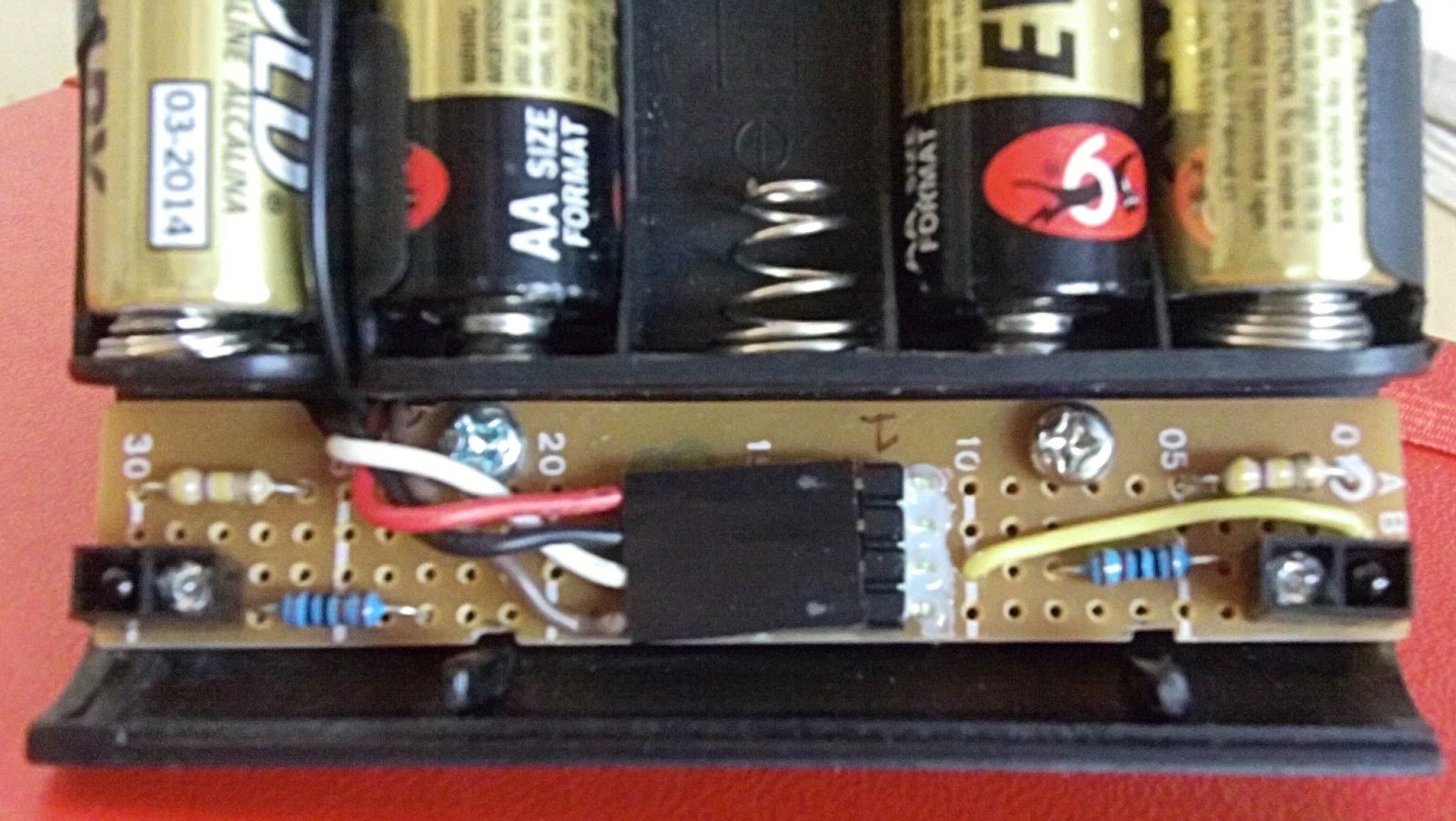
For the four pin header instead of my usual molex connectors I used a standard right angle connector and the new headers I had recently purchased from Little Bird Electronics. These headers are smaller than the molex ones but don't have a guide slot so can be inserted either way (and also the wrong way).
Once everything was soldered I drilled two holes mounting holes and tapped threads into the chassis. All this drilling and tapping makes for a much better result but adds to the time. Once a hole and drilled and tapped, then the bolt has to be cut to size as it can't come past the other side of the chassis base plate. Much trial and error and test fits and cutting involved. With the holes ready I used nylon spacers between the board and the chassis to get the position I wanted.
Lastly I made a 4 wire cable to connect to the main board. Originally I started crimping a ribbon cable but then thought I was sure I already had a cable with a header on it in my salvage box. Sure enough I did although the four header socket only had three wires. Still saved some time and crimp pins.
After doing continuity test and shorts circuit tests I wired up the board to my bread board circuit and it worked fine. Well it did until a further integration test showed the board and thus the sensors were too close to the ground. The sensor voltages were only differing from 0.3V to 0.1v between the black surface and the white edge. At the distance to the ground (under 3mm) even the flat black of the sumo ring was being detected. This was solved by cutting the nylon spacers in half and reattaching the board. With about 5mm distance between the board and the ring I was getting the behaviour and voltage differences I wanted. Next was onto the real work, the main board.
No comments:
Post a Comment